I’ve decided to try to learn electronics, and for this, I will of course need to interact with hardware (cables, resistors, diodes, etc…), but I’m lucky I was born in a time when a great deal of circuit design can be done from a computer using specialized software.
Being very new to this world and a stubborn Linux user, I did a quick search to try to find what’s my best option. I stumbled into this Electronics Circuit Simulator Software comparison page in Wikipedia.
I mainly looked at 3 things:
- Compatible with Linux
- Latest release date
- Open source
With these simple requirements, I found two contenders:
Qucs-S has a nice graphical user interface, but depends on a SPICE back-end (e.g. Ngspice) to run. Due to this dependency, I’m going to be required to learn Ngspice anyway, so I decided to start with this one.
SPICE (Simulation Program with Integrated Circuit Emphasis)
SPICE is an Open Source command line application that can be used to run simulations of electrical circuits.
SPICE also defines a syntax to model circuits using only text files; This format is the industry standard, which makes it good for sharing designs between systems, but it doesn’t provide a graphical user interface, which makes it hard to use by humans.
Ngspice
Ngspice claims to be the successor of the original SPICE. Like SPICE, it doesn’t provide a graphic interface for creating circuits, but there are many tools that use Ngspice as their back-end.
Input format
Ngspice doesn’t provide a graphical interface, instead, it relies on text to describe circuits. In this section we are going to learn the basics of this syntax. For more in-depth explanations, it’s better to check the Ngspice documentation.
Ngspice doesn’t care about the extension of the files it analyses, but it’s common to use the .cir or .spice extensions.
The first line of the file must be the title of the circuit and the last line must be .end followed by a newline character.
Elements of a circuit (Voltage sources, resistors, capacitors, etc…) are specified by a line starting with a letter representing type of element (R = Resistor, C = Capacitor, etc…). Each type of element follows a different syntax, for voltage sources, for example, this is the syntax:
1
V(name of source) (where the positive pole is going to be connected) (where the negative pole is going to be connected) (number of volts it provides)
If we want to simulate a 9V battery, we can use this line:
1
Vbattery 1 0 9
Here we are naming our voltage source battery and specifying that it provides 9 volts. 0 means that we are connecting the negative pole to ground. 1 is just an identifier for another bus (cable). How these identifiers work will be easier to understand when we start creating circuits.
Simulating circuits
One of the simplest circuits we can build is a voltage divider. A small circuit that produces an output voltage that is a fraction of the input voltage. The diagram for a voltage divider looks like this:

As we can see in the image, we have one voltage source and two resistors. We can model this simple circuit with spice like this:
1
2
3
4
5
Voltage divider
V1 Vin 0 9
R1 Vin Vout 1k
R2 Vout 0 2k
.end
Some things to notice about the example above:
- The first line “Voltage divider” is the title of the circuit
- The second line starts with the letter
V, which means we are defining a voltage source- The number
1is just an identifier for the voltage source Vinis a name we are giving to the cable we are connecting to the positive pole0means the negative pole will be connected to ground9means it will provide 9 volts
- The number
- The third line starts with the letter
R, which means we are defining a resistor- The number
1is just an identifier for the resistor Vinmeans one side of the resistor will be connected to the positive pole of our voltage providerVoutmeans the other side of our resistor is connected to a cable we’re callingVout1kmeans it’s a 1000 ohm resistor
- The number
- The fourth line is another resistor
- The number
2is the identifier - One side is connected to
Vout - The other side is connected to
0(ground) 2kmeans it’s a 2000 ohm resistor
- The number
- The fifth line is the mandatory
.endto denote the end of the circuit
We have defined a circuit using Ngspice’s format, now we need to tell Ngspice what we want to simulate. To do this, we can add a control section to our circuit definition.
For this simple example, we are only interested in the voltage we are going to get at Vout, so this simple modification suffices:
1
2
3
4
5
6
7
8
9
10
11
Voltage divider
V1 Vin 0 9
R1 Vin Vout 1k
R2 Vout 0 2k

.control
op
print Vout
.endc

.end
In this updated version, we can see the .control keyword in line 6. This specifies the beginning of control instructions (things we want to analyze). In line 9 we finish our definition of instructions using .endc.
In line 7 we start by defining an operating point. In this case we just let Ngspice use the defaults.
In line 8 we instruct Ngspice to print the voltage at Vout.
If we save this file as voltage-divider.cir, we can use ngspice to run the simulation:
1
2
3
4
5
6
7
8
9
10
11
12
13
14
15
16
17
18
19
20
21
22
23
ngspice voltage-divider.cir

******
** ngspice-40 : Circuit level simulation program
** The U. C. Berkeley CAD Group
** Copyright 1985-1994, Regents of the University of California.
** Copyright 2001-2023, The ngspice team.
** Please get your ngspice manual from https://ngspice.sourceforge.io/docs.html
** Please file your bug-reports at http://ngspice.sourceforge.net/bugrep.html
** Creation Date: Mon Jun 12 16:33:44 UTC 2023
******

Note: No compatibility mode selected!


Circuit: voltage divider

Doing analysis at TEMP = 27.000000 and TNOM = 27.000000


No. of Data Rows : 1
vout = 6.000000e+00
ngspice 1 ->
What we are interested in is vout = 6.000000e+00, which tells us that the voltage at Vout is 6 volts (6.000000 * 10^0).
This might not seem like much, but it allows us to see how a circuit will behave without having to get all the electronic components, build the circuit manually and then having to check the voltage with a multimeter.
Simulating an oscilloscope
In the previous section we were able to prescind of a multimeter. We can also do more complex observations that vary over time, like if we were using an oscilloscope.
To show how this looks like we will change our voltage source to a pulse voltage:
1
V1 Vin 0 dc 0 PULSE (0 9 0 1u 1u 2u 5u)
This is a lot more complex than our previous example, so let’s take a closer look:
- The number
1is just an identifier for the voltage source Vinis a name we are giving to the cable we are connecting to the positive pole0means the negative pole will be connected to grounddcmeans this is a direct current source0doesn’t mean anything in this case since the voltage will be controlled by the pulsePULSEdefines a pulse voltage, let’s look at the values inside the parentheses:0- Initial value of the voltage9- Pulsed value of the voltage0- Time it will take for the first pulse to kick in1u- Time it takes to get from the initial value to the pulsed value1u- Time it takes to get back from the pulsed value to the initial value2u- How long will the pulse last5u- After how long the pulse be emitted again
To see a plot of how this behaves, lets create a new file named voltage-divider-pulse.cir, with this content:
1
2
3
4
5
6
7
8
9
10
11
Voltage divider
V1 Vin 0 dc 0 PULSE (0 9 0 1u 1u 2u 5u)
R1 Vin Vout 1k
R2 Vout 0 2k

.control
tran 1u 20u
plot Vout
.endc

.end
Instead of op, we use tran. In this case want to plot what happens every 1u for 20u. Then we tell Ngspice which values we want plotted (plot Vout).
If we run Ngspice for this file, we will get a pop up window with this graph:
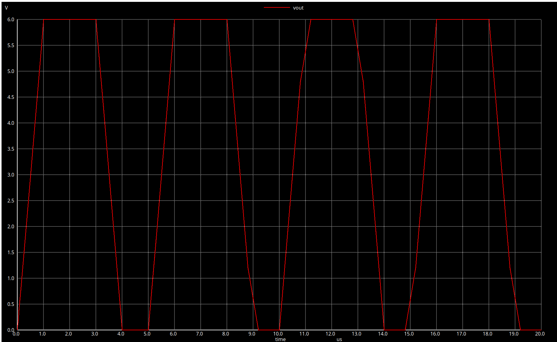
We can see in the graph that the voltage goes up to 6 volts and stays there for 2u, but it goes back down to 0 when the pulse is not on.
Conclusion
In this article we learned how to model simple circuits with Ngspice and how we can use control statements to see how those circuits are behaving. You can find the full examples in Github.
electronics