I started learning electronics a few days ago and I’m seeing resistors in every diagram I find and using them in pretty much all my experiments. So far, I’ve been using them blindly, but in this article I’m going to try to get a better understanding of what they actually do.
Electrical Resistance
A resistor is a component that implements electrical resistance. Electrical resistance is usually explained using a water and pipes analogy.
Let’s start by imagining two containers; One full of water and the other one completely empty:
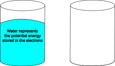
This will be analogous to the two poles of a battery. One of them contains more electrons (water) than the other. While the two containers are not connected, water doesn’t flow.
Let’s now connect the two containers, but we’ll do it with an obstructed hose, so water can’t go through:
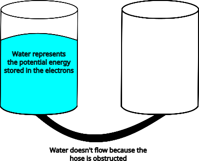
This is similar to connecting the poles of a battery with an insulator (e.g. Rubber).
If we want water to flow from one container to the other, we can connect them with an unobstructed hose:
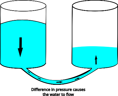
Since the water in the left container is creating more pressure, the water will start flowing to the other container as soon as they are connected. When both containers have the same amount of water, equilibrium has been reached and water stops flowing.
Ohm’s Law
To understand better how resistors work, it’s necessary to get familiar with Ohm’s law. It states that the current flowing through a conductor (or resistor) is directly proportional to the voltage applied to that conductor. This can be summarized with the formula:
1
V = IR
Where:
V- Voltage between the two ends of the conductor (Volts)I- Current flowing through the conductor (Amps)R- The resistance applied by the material (OhmsΩ)
With this law at hand, we can continue with our analogy.
We have our two water containers and one of them has higher pressure than the other (voltage); The two containers are connected by a hose (conductor or resistor):
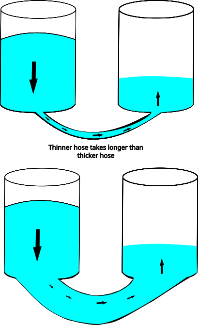
A wider hose allows water to flow faster (lower resistance) and a thinner hose makes water flow slower. This is similar to the way cables behave. Thicker cables generate less resistance than thinner cables.
If we wanted to know how much resistance is being generated by a cable (or resistor) we can measure the current after the resistor and use this formula:
1
R = I / V
In the real world, it’s more common that we have a source of voltage and we want to reduce the voltage or current to some desired values. Then we use this formula to calculate how much resistance we need.
A word about short circuits
A short circuit allows current to travel through a path with very low resistance. An example of such path would be connecting the two poles of a battery with a cable. We can apply Ohm’s law to see what would happen.
Let’s say we have a 9V battery that can provide 1 ampere for 1 hour. We also have a short copper cable that has a resistance of 1 Ω. We can now use Ohm’s law to calculate the current flowing through the resistor:
1
2
3
4
5
I = V / R

I = 9V / 1Ω

I = 9A
The result is 9A, which means our circuit will consume 9 amperes. We mentioned that our battery can provide 1A for 1 hour, this is the same as saying 3,600 amps in total for 3,600 seconds. A simple division can give us how long until we drain the battery:
1
3600 / 9 = 400
This means our battery would last 400s or approximately 6.7m. This is very little time for a battery to last, so we can conclude that one side effect of a short circuit is that it drains a battery very quickly; but there are other more dangerous side effects.
When we transport current (amperes) through a material, heat is generated. The higher the current, the higher the temperature. If we made this experiment with a battery, our cable would probably get a little warm and nothing else would happen, but if we used a higher voltage, the current would also go up:
1
2
3
4
5
I = V / R

I = 100V / 1Ω.

I = 100A
The amount of current would be so high that it would burn the cable and explode. Explosions can destroy things around them, so it’s very important to be careful when dealing with high voltage.
Resistors in the real world
Resistors come in a few presentations, but the most common ones are Carbon Composition Resistors (CCR), which look like this:
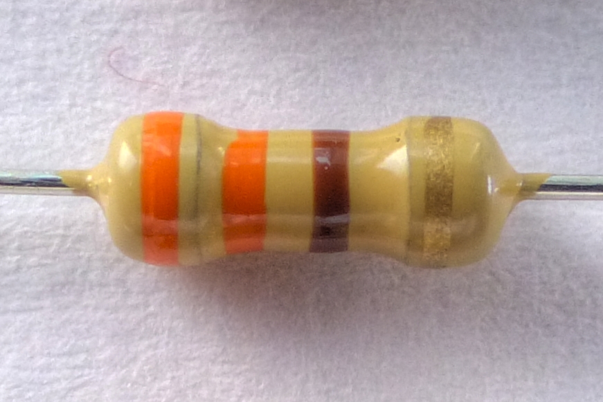
We can see that these resistors have lines of different colors. These lines signify their resistance value in Ohms. This diagram explains what the colors mean:
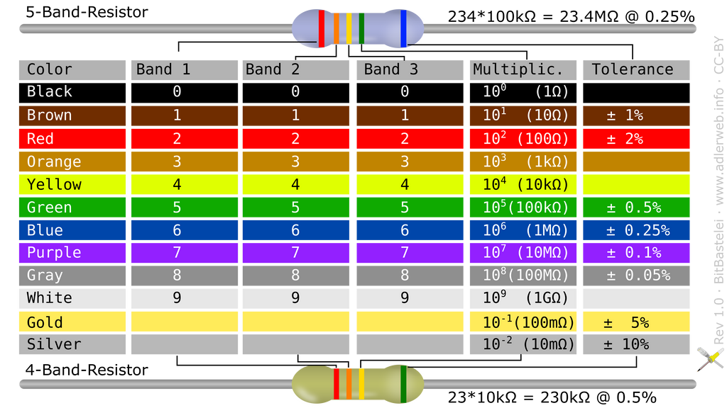
Notice that there are resistors that contain 5 bands (example at the top of the image) and others that contain 4 bands (example at the bottom).
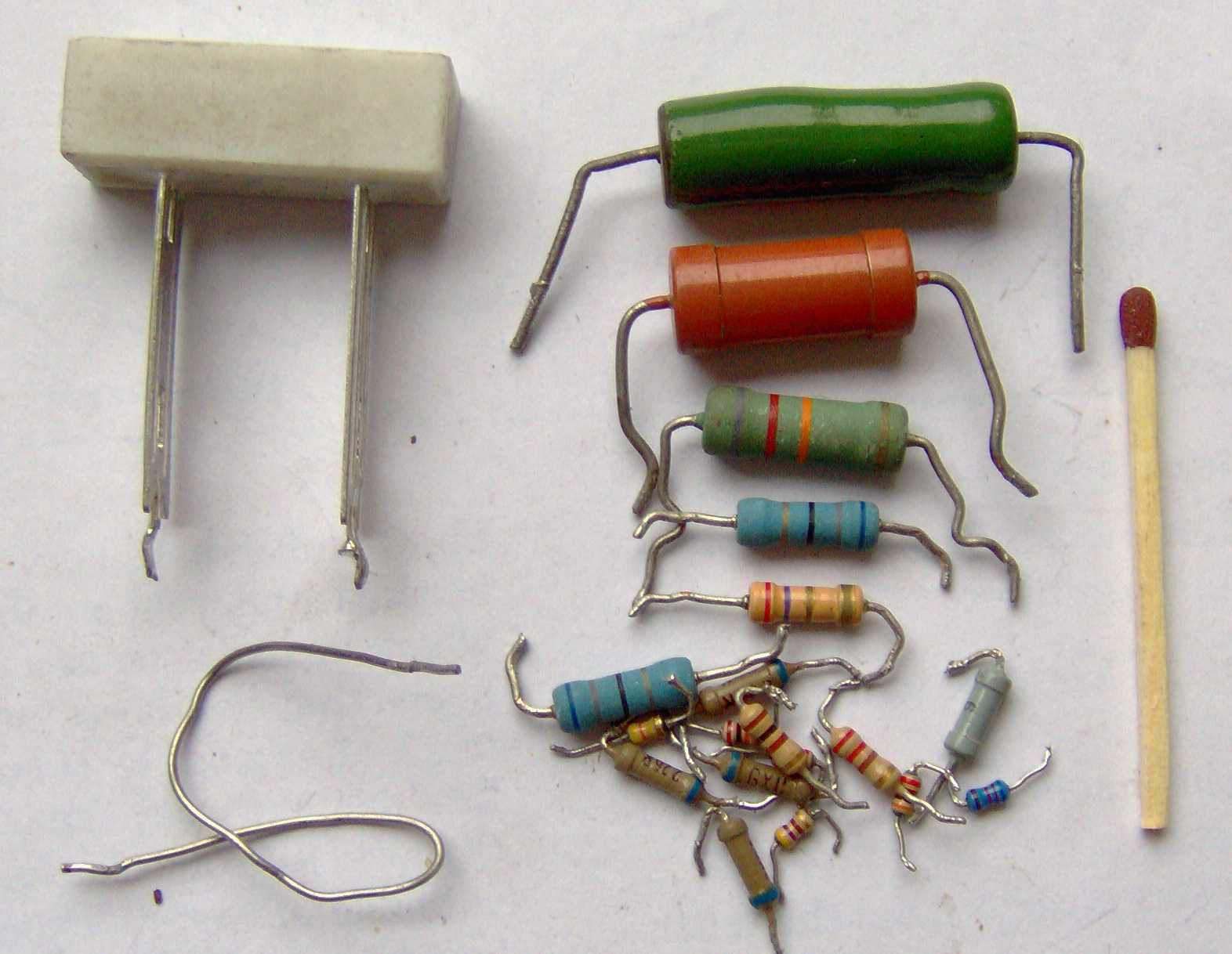
Resistors come in various other formats, but those are easier to read since they usually have their resistance value printed on them. Some of them are shown in the following image:
Another important property of resistors is their power rating. This value is expressed in Watts.
Together with their resistance value, resistors also specify their power rating (e.g. 1/8 Watts, 1/4 Watt, etc). When using a resistor we need to make sure we are not running more power than its power rating, or it can overheat and explode.
We can measure how much power we are running through a resistor if we know the voltage being applied:
1
P = V²/R
Let’s say we connect a 470Ω resistor to a 9V battery:
1
2
3
4
5
P = (9V)² / 470Ω

P = 81V² / 470Ω

P = 0.17234 Watts
Since the resulting power consumption is 0.17234W we can use a resistor with a power rating of 1/4W (0.25W). If we tried to use a resistor with a power rating of 1/8W (0.125W) it would most likely burn.
Resistors in diagrams
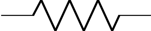
When designing or reading diagrams, we’ll encounter resistors represented by one of these symbols:
ANSI style symbol:
IEC style symbol:
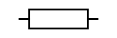
The value of the resistors will usually be expressed textually next to the component in question.
Conclusion
In this article we learned how resistors work using a commonly used hydraulic analogy. This analogy allows us to create an intuition of how electricity works even though it can’t be seen.
We also learned about resistors in the real world, their characteristics and how they behave when connected to real circuits.
electronics