I’m working on a circuit where I need to use a sensor that mentions using an open collector (Also known as: open drain, open emitter or open source) output. In this post, we are going to learn what this is and how to use open collector components.
The term open in open collector refers to an “open” digital circuit. Which means that a pin in our component is not connected to a HIGH or a LOW signal. It is, effectively, undefined.
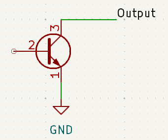
When we have an open collector output, the output will toggle between LOW and undefined. This happens, because of the way the component is connected internally, which often looks like this:
When the voltage on the base of the transistor is LOW, the transistor will be off, and the collector will be open (That’s where the name comes from). This gives us a floating signal.
When the voltage on the base of the transistor is HIGH, it will be on, and the collector will be connected to GND, which gives us an effective LOW state.
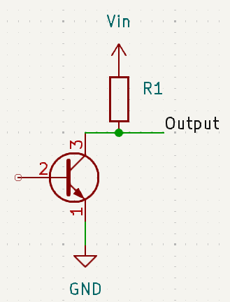
To convert the floating state to an affirmative HIGH, we would need a pull-up resistor:
Reason for open collector
Having an open collector output, forces us to add a pull-up resistor and might give us a confusing output, so, why do manufacturers do this?
The main reason is signal flexibility. If we were using a sensor that works with 5v, and toggled between 5v or GND, we wouldn’t be able to connect this sensor to a 3.3v IC.
On the other hand, when a sensor uses an open collector, it doesn’t matter the voltage of the sensor. We can connect the output to our desired voltage, and we would get the desired behavior.
electronics 
