I’m building a project for an ESP32 microcontroller (which works with 3.3v logic), and my project needs to get information from a 5v sensor.
Connecting the 5v directly to a GPIO (General Purpose Input/Output) pin would probably damage the chip. To prevent this, we can use a voltage divider to lower the voltage.
Voltage dividers
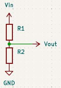
A voltage divider is a simple circuit that given an input voltage, it produces a lower output voltage. A simple representation looks like this:
Kirchhoff’s Laws
Kirchhoff’s Laws are fundamental to understand a lot a electric circuits. For our voltage divider, they will help up determine the values of our resistors.
Kirchhoff’s Current Law (KCL)
Kirchhoff’s Current Law (KCL) states:
The current flowing into a node must be equal to the current flowing out of it
In our voltage divider, since we only have one node (one path for the current to follow); the same amount of current flows through both resistors.
Kirchhoff’s Voltage Law (KVL)
Kirchhoff’s Voltage Law (KVL) states:
The directed sum of the potential differences (voltages) around any closed loop is zero.
In Layman’s terms: When we have a closed circuit, if we measure the voltage in all segments of the circuit and then add those measurements, we’ll get 0 as a result.
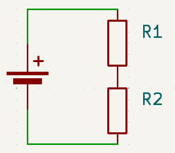
Let’s re-draw our voltage divider as a closed circuit:
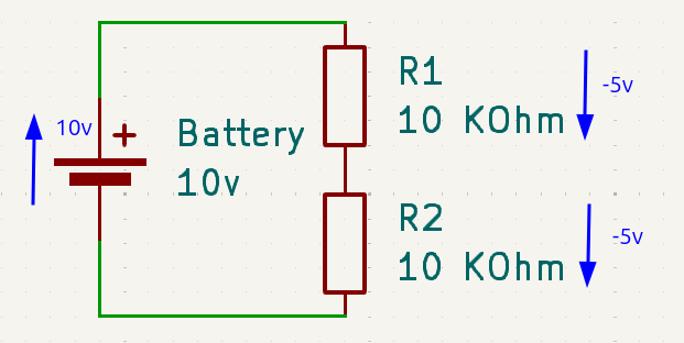
If we assign values to the battery and the resistors, we can measure the voltage in all segments of the circuit:
In this image, we can see that the battery gives us 10 volts, R1 drops 5 volts and R2 drops another 5 volts. This follows KVL.
Voltage divider formula
We use Kirchhoff’s Laws and Ohms law to derive a formula that allows us to choose the correct resistors to obtain a desired voltage given an input voltage.
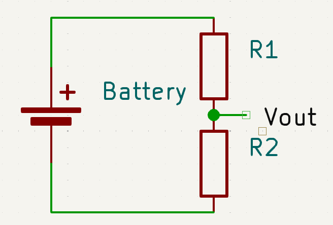
Let’s take another look at our circuit:
Given KCL, we know that the same current goes through R1 and R2:
so:
1
I1 = I2
Since we want to be able to express Vout in relation to Vin, R1 and R2, we can start by using Ohm’s law on Vin:
1
Vin = I・(R1 + R2)
From this, we can solve that:
1
I = Vin / (R1 + R2)
We can also apply Ohm’s law to Vout:
1
Vout = I・R2
If we replace I, we get:
1
2
3
Vout = (Vin / (R1 + R2))・R2

Vout = (Vin・R2) / (R1 + R2)
Which is the general formula for a voltage divider consisting of two resistors. We generally find it in this form:
1
Vout = (R2/(R1 + R2))・Vin
Building our voltage divider
In my case, I know the input voltage is 5v and my desired output voltage is 3.3v, so we can use some algebra to figure out the values for the resistors:
1
2
3
4
5
6
7
8
9
10
11
12
13
14
15
16
17
3.3 = (R2/(R1 + R2))・5

R2/(R1 + R2) = 3.3 / 5

R2/(R1 + R2) ≈ 0.66

R2 ≈ (R1 + R2)・0.66

R2 ≈ (0.66・R1) + (0.66・R2)

0.66・R1 ≈ R2 - (0.66・R2)

0.66・R1 ≈ 0.34・R2

R1 ≈ (0.34・R2) / 0.gg

R1 ≈ 0.515・R2
The result gives us the ratio between R1 and R2. To calculate the actual values, we need to take into account the current delivered by the sensor we are using and the current we can deliver to the microcontroller.
The sensor I’m using specifies a 15 mA maximum working current, so we need something lower than this. The ESP32 specifies a high-level input current of 50 nA, so we need to keep our current around this value.
Using the current value of 50 nA and the fact that we want a voltage drop of 1.7v (5v - 3.3v), we can get the value of R1 following Ohms law:
1
2
3
4
5
6
7
V = IR

R = V / I

R = 1.7v / 0.000000005A

R = 340,000,000 Ohms = 340 MOhms
This very high resistor value is not practical, since it’s not easy to find 340 MOhm resistors. Usually the highest resistor value that is easily available is 1 MOhm, and since R2 needs to be larger than R1, we better stick to this value or something smaller for R2.
1
2
3
4
5
R1 ≈ 0.515・(1 MOhm)

R1 ≈ 0.515 MOhm

R1 ≈ 515 KOhm
The commercially available resistor value closest to 515 KOhm is 470 KOhm, so let’s see what happens if we use these two values:
1
2
3
4
5
6
7
8
9
Vout = (Vin / (R1 + R2))・R2

Vout = (5v / (470,000 Ohm + 1,000,000 Ohm))・1,000,000 Ohm

Vout = (5v / 1,470,000 Ohm)・1,000,000 Ohm

Vout = (0.00000340136 A)・1,000,000 Ohm

Vout ≈ 3.401 v
Which is well within the range for HIGH signal on an ESP32: 2.7v to 3.6v.
Now that we know the voltage and the resistors values, we can also calculate the current used by the circuit:
1
2
3
4
5
6
7
8
9
Vin = I・(R1 + R2)

I = Vin / (R1 + R2)

I = 5v / 1,470,000 Ohm

I ≈ 0.00000340136 A

I ≈ 3.4 µA
Conclusion
Being new to electronics, the hardest part for me was figuring out the values I need from the datasheet.
Once we have those values, we just need to plug them into the voltage divider formula and round to available resistor values.
electronics esp32 


