If you need a reminder about resistors in general, you can take a look at my resistors article.
Floating pins
Pull resistors are used to solve the problem of floating pins, so let’s briefly explain what that is.
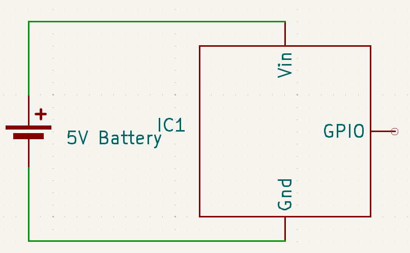
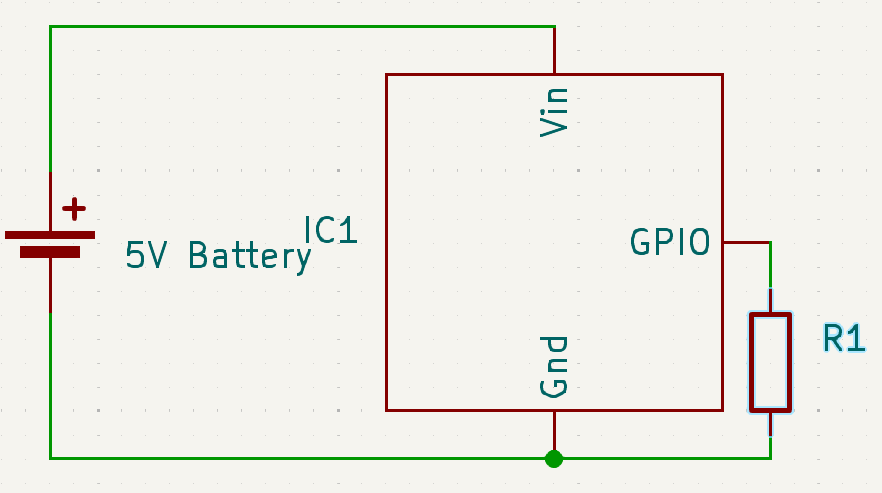
In the following diagram, we have a simple IC (Integrated Circuit) that works with 5V and has a single GPIO (General Purpose Input/Output) pin:
If we use the GPIO pin for input, it will read HIGH or LOW depending on the input voltage.
The problem is that if we write a program that reads from the GPIO pin while it is floating (not connected to anything), the value we’ll get is undefined. This happens because there are magnetic fields everywhere that can affect the reading.
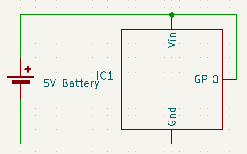
To prevent these undefined readings, we need to provide a well-defined input. If we want a HIGH, reading, we could connect it directly to the positive pole of the battery:
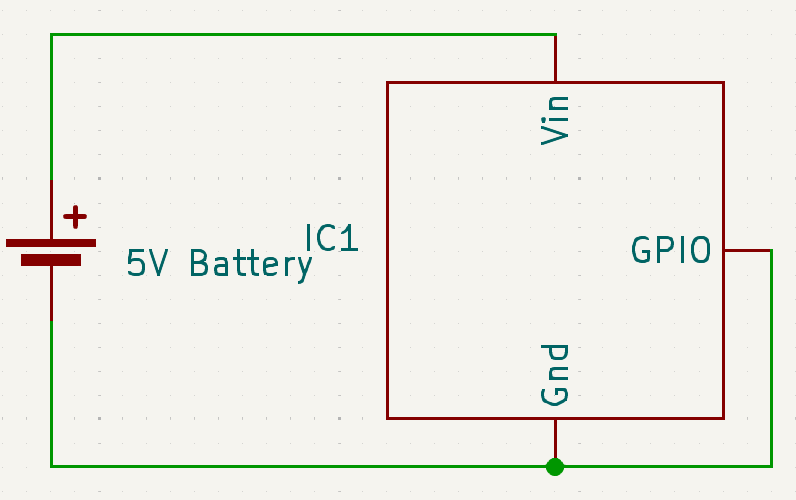
If we want a LOW, we can connect to the negative pole of the battery:
In a more realistic scenario, the input will not always be the same. The simplest scenario would be having a switch that toggles between HIGH and LOW.
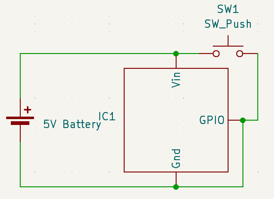
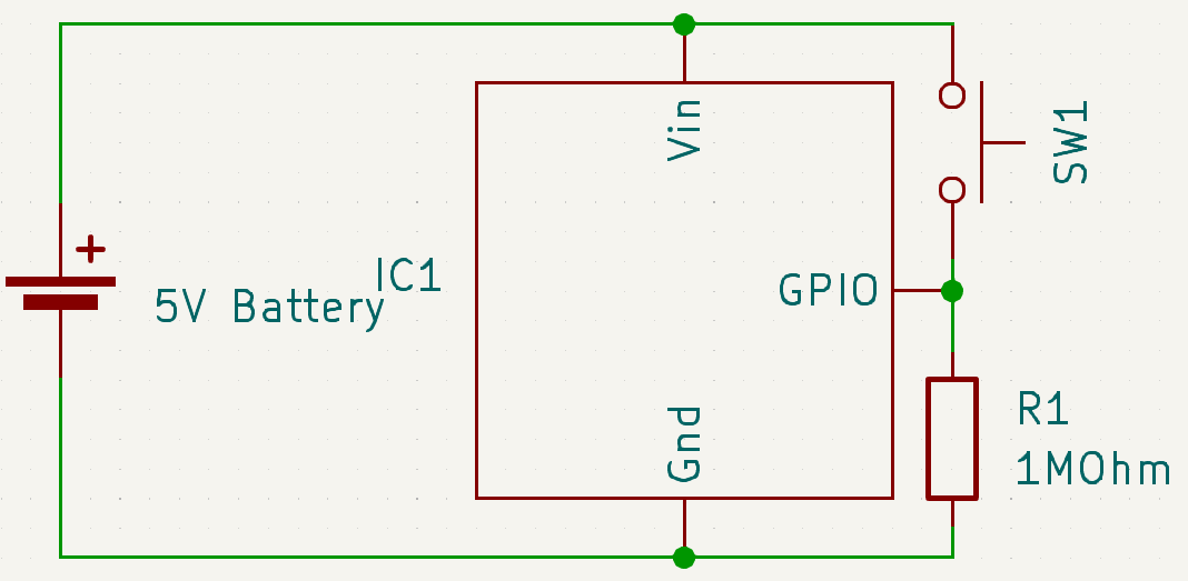
If we want the input to be normally LOW and become HIGH when we push the button, we might naively try this, but it would be wrong:
The input will correctly report LOW initially, but as soon as we push the switch, we would be joining Vin and Gnd, causing a short circuit. To prevent the short circuit, we can use a pull down resistor.
Pull down resistor
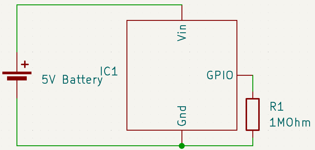
A pull resistor is a resistor inserted between the GPIO pin and the negative pole, like so:
In this case, GPIO, will read LOW. The same as when the resistor wasn’t there. Of course, having a resistor is not the same as not having a resistor, so let’s try to understand what is happening here.
We will need some information about our IC. This information should be included in the corresponding datasheet.
Because this is an input pin, we need to know the input leakage current for our IC. Let’s say the datasheet gives us a value of 500 nA (0.000,000,5 A).
Because this is a pull down resistor, we also need to know the Input low voltage, which is the range that our IC considers a LOW. Let’s say, anything between 0v and 1v is considered a LOW.
We can now apply some guesswork and Ohm’s Law (V = IR) to find a good value for the resistor.
Let’s start with a 10 MOhm (10,000,000 Ohm) resistor.
1
2
V = 0.000,0005 A x 10,000,000 Ohm
V = 5v
5v is far from our higher limit of 1v, so let’s try a lower one: 1 MOhm (1,000,000):
1
2
V = 0.000,0005 A x 1,000,000 Ohm
V = 0.5v
0.5v is right in the middle of our range, so it looks like a good value. We don’t want a value of 1v, because it’s too close to the limit and any little fluctuation would make the voltage incorrect.
Unfortunately, the world of hardware is hard, so this simple math, is not enough. We need to account for magnetic fields that could interfere with our circuit. It’s nearly impossible to know what magnetic fields will be present wherever we deploy our project, so it’s good to have extra wiggle room. For now, we’ll go ahead with our 1 MOhm resistor.
By itself, it looks like it doesn’t give us much, but this allows us to solve the switch problem:
When the switch is not pressed, it works the same as if the switch wasn’t there.
When the switch is pressed, we don’t have a short circuit anymore because the resistor drops the voltage. In that case, GPIO has a direct connection to Vin (5v) so it will read as HIGH.
Pull up resistor
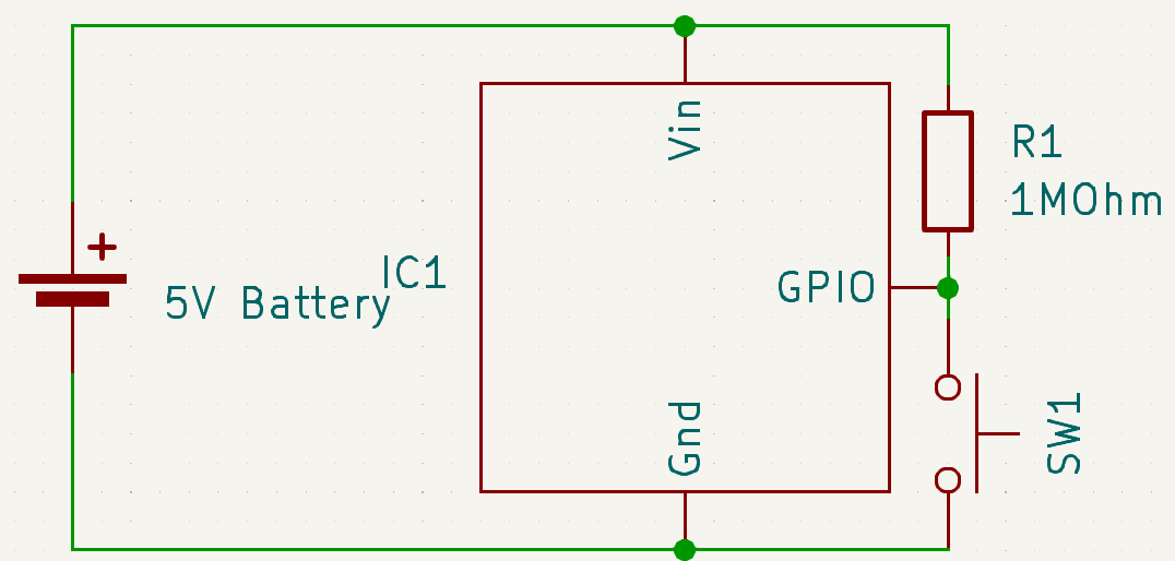
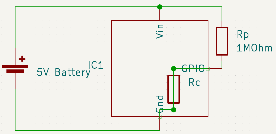
A pull up resistor is very similar to a pull down resistor. The difference is that the resistor is connected to Vin instead of Gnd:
In this case, we need to pay attention to the Input high voltage. Let’s say, for our IC, it’s between 4v and 5v.
To verify that our resistance is correct, we’ll need to take into account that the IC has an internal resistance:
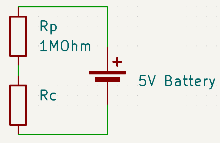
The resistance of the IC is not actually a resistor, but the resistance it has to apply to drop the voltage to Gnd. For analysis’ sake, we can simplify the circuit to this:
Since the leakage current is the same, we already know the voltage drop for our 1 MOhm resistor:
1
2
V = 0.000,0005 A x 1,000,000 Ohm
V = 0.5v
This means, the voltage after the resistor will be:
1
5v - 0.5v = 4.5v
Which is acceptable for our example. The rest of the voltage is dropped by the IC’s internal resistance.
Conclusion
I see pull resistors used in a lot of beginner projects involving microcontrollers, but very few places explain how they work and why they chose the resistor they chose. I hope this brings some clarity to the topic.
electronics esp32 